Sodera Conductive Testing
Test Equipment
While exact conductive test setups are dependent on the specific circumstances surrounding the DUT (Device Under Test) RF interface, the following equipment is required for most testing situations.
- Coaxial cable with adapter for connecting to DUT 1.
- Coaxial cable with adapter for connecting to DUT 2.
- Coaxial T-connector.
- SMA adapters for connecting coaxial cable or attenuators to the ComProbe antenna connectors.
- Attenuators, values depending on the Bluetooth technology or DUT power output levels.
-
Sodera Wideband Bluetooth Protocol Analyzer.
- Personal computer for running Frontline software.
Configure the Sodera Unit
To protect the DUTs and the Sodera hardware, it is essential to understand the DUT power output. As a starting point for conductive testing the Sodera hardware should be configured for a lower sensitivity.
- With the Sodera unit connected to the personal computer with Frontline software running, select Capture Options from the Options menu.
-
In the Capture Options Settings check the Radio section box Reduce RF sensitivity (20 dB reduction). This selection will place a 20 dB attenuator in the path of the antenna jack.
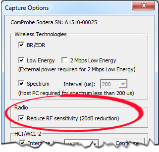
Sodera Capture Options dialog Radio setting option
- Click the OK button and the settings will be saved to the connected Sodera hardware.
- This is a cautionary first step, but reducing the Sodera hardware sensitivity may place too much attenuation in the signal path. Should the capture results prove to be ineffective try removing the attenuator to increase the Sodera hardware sensitivity.
Test Setup
"Sodera Conductive Test Setup" shows the conductive test setup. The values of AT1, AT2, and AT3 depend on the power transmitted by DTU 1 and DTU 2. If the Sodera unit was configured for reduced sensitivity, then AT3 may not be necessary.
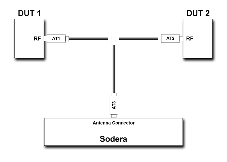
The AT1 through AT3 attenuator values will depend on the DUT1 and DUT2 transmitter Class or the transmit power from each device. At higher power levels all three attenuators may be needed. In all cases, use good engineering practices to protect the devices under test and the Sodera hardware from damage, and to ensure reliable operation.
For example, assume that there is no attenuation in the test setup:
- At the T-connector the power will split in half. For example, if DUT1 is a Class 1 device transmitting +20 dBm (100 mW), at the T-connector it will split with +17 dBm (50 mW) going to DUT2 and +17 dBm (50 mW) going to the Sodera antenna connector. Adding additional attenuation with AT1, AT2, AT3, and the Capture Options Radio selection will further reduce theinput power level to the Sodera.radio.
- If DUT1 or DUT2 is a Class 2 device, +10 dBm (12.5 mW) will reach the Sodera antenna connector. If they are Class 3 devices, -3 dBm (0.5 mW) will reach the antenna connector.
If the protocol analysis results prove to be unreliable, adjust the AT1, AT2, or AT3 values and the Sodera Capture Options Radio settings to achieve reliable results.